SPRAYBOOTH FILTER APPLICATION(ceiling filter and paint stop filter)
Before leak detection, prepare the high-efficiency filter PAO. Remove the diffuser of the high-efficiency filter, clean the outer surface of the housing and frame, to prevent dust from interfering with the detection. Turn off the fire alarm device in the cleanroom (area) to avoid misunderstanding due to smoke leakage during the test.
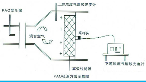
Determine the upstream concentration verification hole. Prepare an inert gas source (usually nitrogen or compressed air). Introduce aerosol smoke into the 4B aerosol generator, add an appropriate amount of PAO liquid, connect the gas source, find the suction port of the fan, and send the aerosol directly to the upstream of the high-efficiency filter through the suction port; turn on the generator switch to turn on the gas source, Adjust the air supply pressure to 20 psig to 30 psig to adjust the aerosol smoke output.
Confirm that the photometer selection valve is in a CLEAR position. Set the power switch to the 1 (on) position, and then press the ENTER key to set the zero reference line. The sampling tube passes through the verification hole, one end is connected to the upstream (high-efficiency filter inlet side) sampling port, and the other end is connected to the aerosol photometer. Set the photometer selector valve to the UPSTREAM position to determine the upstream aerosol concentration. Adjust the opening of the output valve of the aerosol generator until it is confirmed that the upstream concentration reaches 20-80 μg/L and remains relatively stable. Press the 100 buttons, then press the ENTER button to set the 100% reference. After successfully setting the 100% baseline, the indicator will flash, indicating that the 0% baseline must be calibrated. Set the selector valve to CLEAR and press ENTER. The 0% baseline is corrected.
Select the valve to be turned, connect the rectangular sampling head to the photometer, scan the entire part of the filter to be inspected, the sealing head and the mounting frame. Scan rate=15÷the size of the scanning probe in the vertical scanning direction.
The scanning speed is about 2cm/s, the scanning is performed back and forth in a straight line, and the scanning coverage slightly overlaps. The sampling probe is about 3cm away from the filter outlet surface and the frame structure. Scanning should be performed on the entire outlet surface of the filter, the periphery of the filter, the seal between the filter frame and the mounting structure, and the mounting interface. When any indication is equal to or greater than the specified limit, the scanning probe should remain in the corresponding position for a long period of time, and it is judged that it is the large value displayed for a long time at that position.
Draw a schematic diagram on the original record, indicating the location of the leak and the large leak value.
Note: During the scanning process, dust should be avoided to interfere with the casing, and the sampling head should not touch the frame of the high-efficiency tuyere or filter. In the middle and at the end of the scan, check the upstream aerosol concentration to determine its stability. When the upstream aerosol concentration changes by more than ±15%, the 100% reference value is reset and traced back. Note 1: After the leak detection test is completed, the verification hole will be properly sealed in time.